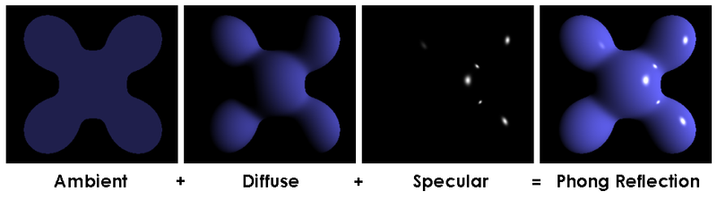
In this article we will continue to implement lighting. We will implement the ambient and specular components of the Phong reflection model, attenuation, and gamma correction.
Accessing The Code
Download all the code as a zip from here: https://github.com/tomdalling/opengl-series/archive/master.zip
All the code in this series of articles is available from github: https://github.com/tomdalling/opengl-series. You can download a zip of all the files from that page, or you can clone the repository if you are familiar with git.
This article builds on the code from the previous article.
The code for this article can be found in the
source/07_more_lighting
folder. On OS X, open the opengl-series.xcodeproj file in the
root folder, and select the target that corresponds with this article. On
Windows, open the opengl-series.sln file in Visual Studio 2013,
and open the project that corresponds with this article.
The project includes all of its dependencies, so you shouldn't have to install or configure anything extra. Please let me know if you have any issues compiling and running the code.
Diffuse Component
We covered the diffuse component in the previous article, but I’ve refactored the code in this article. The new GLSL looks like this:
vec3 normal = normalize(transpose(inverse(mat3(model))) * fragNormal);
vec3 surfacePos = vec3(model * vec4(fragVert, 1));
vec4 surfaceColor = texture(materialTex, fragTexCoord);
vec3 surfaceToLight = normalize(light.position - surfacePos);

float diffuseCoefficient = max(0.0, dot(normal, surfaceToLight));
vec3 diffuse = diffuseCoefficient * surfaceColor.rgb * light.intensities;
The diffuseCoefficient was previously called brightness. It uses the max
function instead of clamp to avoid negative values.
Also, because normal and surfaceToLight are both unit vectors, the dot
product code was simplified from this:
dot(normal, surfaceToLight) / (length(normal) * length(surfaceToLight))
down to this:
dot(normal, surfaceToLight)
Ambient Component
The ambient component of the Phong reflection model basically specifies a minimum brightness.
The ambient component of the Phong reflection model basically specifies a minimum brightness. Even if there is no light hitting a surface directly, the ambient component will light up the surface a little bit to stop it from being pure black. The ambient brightness is constant for all surfaces.
We will calculate the ambient component using a percentage of the original
intensities of the light source. We will store this ambient percentage as a
float with a value between zero (0%) and one (100%), in a variable named
ambientCoefficient. For example if ambientCoefficient is 0.05 (5%) and the
reflected light intensities are $$(1, 0, 0)$$, which is pure red light, then
the ambient component will be $$(0.05, 0, 0)$$, which is very dim red light.
The GLSL to calculate the ambient component in the fragment shader looks like this:
vec3 ambient = light.ambientCoefficient * surfaceColor.rgb * light.intensities;
This is the same as the diffuse component we implemented in the last article,
except that we use light.ambientCoefficient instead of brightness (which is
now called diffuseCoefficient).
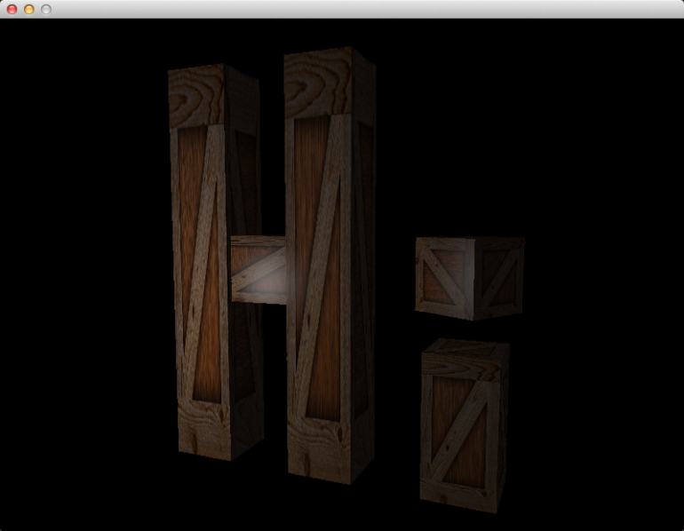
Specular Component
The specular component is what makes a surface look shiny.
The specular component is what makes a surface look shiny. The word “specular” means “like a mirror,” and it is used here because the shiny patches (a.k.a. specular highlights) are fake reflections of light, like a mirror would reflect light.
Let’s start by looking at how a mirror reflects light.
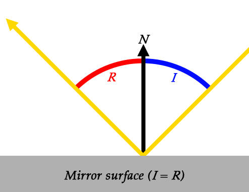
$$N$$ and $$I$$ are the normal and the angle of incidence (AoI), which we saw in the last article. $$R$$ is new, and it represents the angle of reflection (AoR). The angle of reflection is the angle between the reflected ray, and the surface normal. It is sort of the opposite of the angle of incidence.
When light hits a perfect mirror surface, the AoI and AoR are equal. That is, if light comes in at a 30° angle, it will be reflected at a 30° angle.
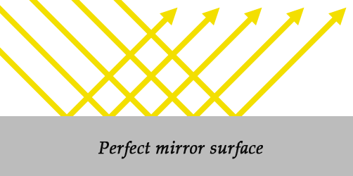
Now let’s look at surfaces that do no behave like a perfect mirror.
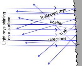
When light hits an irregular surface, like the one shown above, the light could be reflected in any direction. This is the difference between the diffuse and specular components: the diffuse component models irregular surfaces, and the specular component models mirror-like surfaces.
Many surfaces have both specular and diffuse components to them. The outer surface of a car is a good example. It’s not a perfect mirror, but it can be shiny enough to see your reflection in it. This is because the surface has a layer of paint underneath a layer of clear topcoat. The paint layer is diffuse, but the topcoat layer is specular. The topcoat is also clear, so some of the light is reflected, but some of the light goes straight through to hit the paint layer beneath.
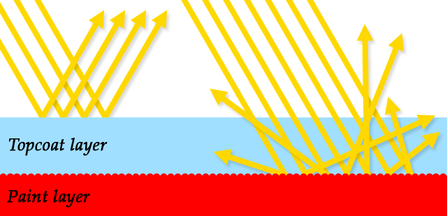
The specular component is usually a different color to the diffuse component.
Notice how when the topcoat reflects light, the rays don’t hit the paint layer. Normally the paint layer would change the color of the light by absorbing some of the intensities, but that can’t happen if the light doesn’t hit the paint. This means that the specular component is usually a different color to the diffuse component. Most specular surfaces don’t absorb anything, they just reflect all of the light, which means the specular color would be white. This is why the shiny parts of a car are white, even though the paint is red.
To calculate the specular component, we basically solve this question: if the surface was a perfect mirror, would it be reflecting rays from the light source straight into the camera? To get the answer, we:
- Calculate the incidence vector, which is a vector from the light to the surface.
- Calculate the reflection vector, based on the surface normal and the incidence vector, using the AoI = AoR rule.
- Calculate a vector from the surface to the camera.
- Get the angle between the reflection vector and the surface-to-camera vector.
- If the angle is small, then we conclude that, yes, the light is being reflected straight into the camera.
Just like the diffuse component, we won’t actually calculate the angle. We will
just use cos(angle) instead, because it ranges from zero to one, which is
more useful.
How small does the angle have to be? Well that depends on how shiny the surface is. We need a variable to represent shininess, and this variable is called the “specular exponent.” The larger the specular exponent, the more shiny the surface will be. It’s up to the artist to play around with this value, until it looks right.
To apply the specular exponent, we take cos(angle) and raise it to the power
of the specular exponent. This produces the “specular coefficient”, which is
the brightness of the reflection.
$$\theta$$ is the angle
$$s$$ is the specular exponent
We will use a GLSL uniform variable called materialShininess to hold the
specular exponent. The GLSL to calculate the entire specular component looks
like this:
vec3 incidenceVector = -surfaceToLight; //a unit vector
vec3 reflectionVector = reflect(incidenceVector, normal); //also a unit vector
vec3 surfaceToCamera = normalize(cameraPosition - surfacePosition); //also a unit vector
float cosAngle = max(0.0, dot(surfaceToCamera, reflectionVector));
float specularCoefficient = pow(cosAngle, materialShininess);

vec3 specularComponent = specularCoefficient * materialSpecularColor * light.intensities;
The incidenceVector is pointing from the light to the surface, which is the
opposite direction of surfaceToLight. There is a GLSL function called
reflect which calculates the reflection vector based on the surface normal
and the incidence vector, using the AoI = AoR rule. We calculate
surfaceToCamera using vector subtraction, and make it a unit vector with
normalize. We then use the dot product to calculate cosAngle, as described
in the previous article. Then, we calculate specularCoefficient by raising
cosAngle to the power of the materialShininess (the specular exponent).
Lastly, we get the whole specular component by multiplying the specular
coefficient by the material’s specular color and the light intensities. This is
very similar to the diffuse and ambient components, except we use
materialSpecularColor instead of getting the surface color from a texture.
In the GLSL code for this article, we actually use a condensed version of the code above. Here is the actual code from the fragment shader:
float specularCoefficient = 0.0;
if(diffuseCoefficient > 0.0)
    specularCoefficient = pow(max(0.0, dot(surfaceToCamera, reflect(-surfaceToLight, normal))), materialShininess);
vec3 specular = specularCoefficient * materialSpecularColor * light.intensities;
Notice the test for diffuseCoefficient > 0.0. This is necessary because the
reflect function will reflect the incidence vector off the front and the
back of a surface. The back sides of a surface don’t receive any light, so
they can’t be shiny at all. The diffuseCoefficient will be equal to zero if
the surface is facing away from the light, so we check that first before
calculating the specular coefficient.
Attenuation
In the code for the previous article, moving the light source away from the wooden crate didn’t make the crate appear any darker. This is obviously wrong, because if you move a candle away from a surface in real life, then the surface gets darker. To fix this, we will implement attenuation. To see attenuation in action, hold down the 1 key, which sets the position of the light, and move the camera further away from the wooden crates. If you do the same thing in the previous article, you will notice that the surface doesn’t get darker, but it does in this article.
Attenuation is the loss of light intensity over distance. The greater the distance, the lower the intensity.
Attenuation is the loss of light intensity over distance. The greater the distance, the lower the intensity. We will represent attenuation as a percentage of remaining light, in a float with a value between zero and one. For example, an attenuation value of 0.2 means that 80% of the light intensity has been lost, and only 20% of the intensity remains.
In the real world, attenuation is proportional to the inverse of the distance squared:
$$d$$ is the distance
We’ll use a modified version of this formula. Firstly, we want to avoid divide-by-zero errors if the distance is zero, so we modify the formula slightly to get this:
$$d$$ is the distance
Now, if $$d$$ is zero, then $$a$$ will be 1, which means that the light is at maximum intensity.
Secondly, we might want to control how fast the intensity decreases over distance. Maybe we want some lights to shine over very long distances without much attenuation, and other lights to only shine short distances with lots of attenuation. To control the attenuation we will add a variable, which we will just call $$k$$:
$$d$$ is the distance
$$k$$ is an arbitrary "attenuation factor"
The formula above, implemented in our fragment shader, looks like this:
float attenuation = 1.0 / (1.0 + light.attenuation * pow(distanceToLight, 2));
The light.attenuation variable is the $$k$$ in the formula above.
We will apply attenuation to the diffuse and specular components, but not the ambient component. Remember that the ambient component is a constant minimum brightness, so it doesn’t make sense to lower the brightness below the minimum.
The GLSL to combine the ambient, diffuse and specular components, including attenuation, looks like this:
vec3 linearColor = ambient + attenuation*(diffuse + specular);
This is almost the final color for the fragment/pixel. The last step is to do gamma correction.
Gamma Correction
All of our lighting calculations so far have assumed that we are working a linear color space. In a linear color space, if you double one of the RGB color values, then the pixel on the screen should be twice as bright. For example, the 100% red color $$(1,0,0)$$ should be twice as bright as the 50% red color $$(0.5,0,0)$$.
The problem is that computer screens do not display colors in a linear color space. The 100% red is actually about 4.5 times brighter than the 50% red, which makes the brightness in the 3D scene look wrong. This is because computer monitors mimic the way that old CRT monitors behaved. I’ve also read that it has nothing to do with CRT monitors, and it’s necessary because of the way that the human eye perceives brightness. Either way, gamma correction will allow us to adjust the brightness of the 3D scene to make it look better.
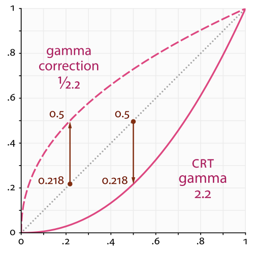
Th dotted line in the middle represents the linear color space we are working in. The solid line at the bottom represents the color space that computer monitors display. Notice how 0.5 on the dotted line matches up to 0.218 on the solid line. This means that if we calculate an RGB value of 0.5, it will actually look like 0.218 when it gets displayed on the monitor, so everything would look too dark. The dashed line at the top represents an RGB value after it has been gamma corrected, which increases the brightness. The gamma corrected color is too bright, and the monitor is too dark, so when they are combined the result looks correct.
Also notice how the lines meet up at zero and one. This means that gamma correction doesn’t affect maximum and minimum brightness – it affects all the shades of brightness in the middle.
Gamma correction is an operation that changes the brightness of an RGB color.
Gamma correction is an operation that changes the brightness of an RGB color. We do all our lighting calculations in linear colorspace, then we do gamma correction to adjust the color before it gets displayed on the screen. This makes all the lighting look correct, instead of looking too dark.
Gamma correction is pretty simple to implement. You take each of the RGB values and raise them to the power of gamma. Some games give the user a brightness setting which allows them to change the gamma value, but we will just use the constant value $$\frac{1}{2.2}$$ in this article, which is the correct value for CRT monitors.
We will do gamma correction using the GLSL function pow. The GLSL looks
something like this:
vec3 gamma = vec3(1.0/2.2);
finalColor = pow(linearColor, gamma);
The pow function raises the first argument to the power of the second
argument. It can take numbers or vectors as arguments. If the arguments are
vectors, it raises each element of the first vector to each element of the
second vector. The code above is just a shorter way of writing this:
vec3 gamma = vec3(1.0/2.2, 1.0/2.2, 1.0/2.2);
finalColor = vec3(pow(linearColor.r, gamma.r),
                  pow(linearColor.g, gamma.g),
                  pow(linearColor.b, gamma.b));
It takes the red, green, and blue components of the linearColor vector, and
raises them all to the power of 1.0/2.2.
After implementing gamma correction and running the program, it actually looks too bright.
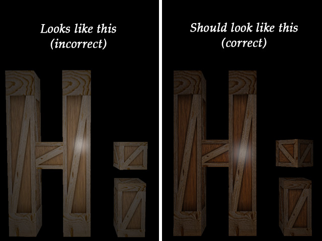
Most image file formats already contain gamma-corrected RGB values.
The gamma-corrected image looks wrong, but the correct image looks like the one
from the last article, which didn’t have any gamma correction. This is because
we’re actually doing gamma correction twice. That’s right, we already had
some form of gamma correction before this article. Most image file formats
already contain gamma-corrected RGB values. The wooden-crate.jpg file that we
use as a texture is already gamma-corrected, and then we gamma-correct it a
second time which makes it look too bright. We could just not implement gamma
correction, which would make the textures look right, but then the lighting
would look wrong.
We will just undo the gamma correction on the texture when we load it.
Thankfully, this is very simple to do in OpenGL. Like most images, our the
wooden crate image is in the sRGB color space, which is already gamma
corrected. We can change the internalFormat argument of glTexImage2D to
tell OpenGL that the texture data is already in the sRGB color space, and
OpenGL will automatically un-correct the pixels into linear color space. For
RGB pixel data, we change the internalFormat from GL_RGB to GL_SRGB. For
RGBA pixel data, we change it from GL_RGBA into GL_SRGB_ALPHA. After making
this change to tdogl::Texture class, the 3D scene looks correct again.
Fragment Shader Code Changes
Here is the entire fragment shader:
#version 150

uniform mat4 model;
uniform vec3 cameraPosition;

// material settings
uniform sampler2D materialTex;
uniform float materialShininess;
uniform vec3 materialSpecularColor;

uniform struct Light {
   vec3 position;
   vec3 intensities; //a.k.a the color of the light
   float attenuation;
   float ambientCoefficient;
} light;

in vec2 fragTexCoord;
in vec3 fragNormal;
in vec3 fragVert;

out vec4 finalColor;

void main() {
    vec3 normal = normalize(transpose(inverse(mat3(model))) * fragNormal);
    vec3 surfacePos = vec3(model * vec4(fragVert, 1));
    vec4 surfaceColor = texture(materialTex, fragTexCoord);
    vec3 surfaceToLight = normalize(light.position - surfacePos);
    vec3 surfaceToCamera = normalize(cameraPosition - surfacePos);

    //ambient
    vec3 ambient = light.ambientCoefficient * surfaceColor.rgb * light.intensities;

    //diffuse
    float diffuseCoefficient = max(0.0, dot(normal, surfaceToLight));
    vec3 diffuse = diffuseCoefficient * surfaceColor.rgb * light.intensities;

    //specular
    float specularCoefficient = 0.0;
    if(diffuseCoefficient > 0.0)
        specularCoefficient = pow(max(0.0, dot(surfaceToCamera, reflect(-surfaceToLight, normal))), materialShininess);
    vec3 specular = specularCoefficient * materialSpecularColor * light.intensities;

    //attenuation
    float distanceToLight = length(light.position - surfacePos);
    float attenuation = 1.0 / (1.0 + light.attenuation * pow(distanceToLight, 2));

    //linear color (color before gamma correction)
    vec3 linearColor = ambient + attenuation*(diffuse + specular);

    //final color (after gamma correction)
    vec3 gamma = vec3(1.0/2.2);
    finalColor = vec4(pow(linearColor, gamma), surfaceColor.a);
}
There is a new uniform called cameraPosition, which is necessary to calculate
the specular component. You may come across other fragment shaders that don’t
have the camera position as a uniform. If the lighting calculations are done in
camera space, instead of world space, then the position of the camera is always
the origin $$(0,0,0)$$. This is fairly common, but we’ll continue to work in
world space for the moment, because it’s a bit more intuitive and similar to
the code in the previous article.
There are two new elements of the Light struct: attenuation and
ambientCoefficient. The attenuation variable is the $$k$$ value we saw in
the attenuation section, earlier in the article. The ambientCoefficient
variable is the percentage of the light to use for the ambient component, also
explained earlier in this article.
There are new material uniforms:
uniform sampler2D materialTex;
uniform float materialShininess;
uniform vec3 materialSpecularColor;
The materialTex variable is the same as tex in previous articles, but has
been renamed to fit in with the other material uniforms. The
materialShininess variable is the specular exponent. The
materialSpecularColor variable determines what light is absorbed and
reflected in the specular calculation. Remember that the specular and diffuse
colors are usually different. The diffuse color comes from the texture
(materialTex), and the specular color comes from this materialSpecularColor
variable.
Material. Unfortunately,
GLSL 1.5 does not allow samplers (such as materialTex) inside
structs, and some drivers would not compile the fragment shader.
The main function of the shader starts by calculating a few variables, and
then each paragraph of code corresponds to a section in this article:
- Calculate the ambient component
- Calculate the diffuse component
- Calculate the specular component
- Calculate the attenuation
- Combine ambient, diffuse and specular components, with attenuation applied
- Perform gamma correction
C++ Code Changes
Most of the changes in this article are in the fragment shader. The C++ changes are only there to set the new uniforms in the fragment shader.
The ModelAsset struct has new variables for shininess and specular color:
struct ModelAsset {
    tdogl::Program* shaders;
    tdogl::Texture* texture;
    GLuint vbo;
    GLuint vao;
    GLenum drawType;
    GLint drawStart;
    GLint drawCount;
    GLfloat shininess; //new this article
    glm::vec3 specularColor; //new this article
};
The Light struct has new variables for attenuation and the ambient
coefficient:
struct Light {
    glm::vec3 position;
    glm::vec3 intensities;
    float attenuation; //new this article
    float ambientCoefficient; //new this article
};
Inside LoadWoodenCrateAsset we set the new material variables:
gWoodenCrate.shininess = 80.0;
gWoodenCrate.specularColor = glm::vec3(1.0f, 1.0f, 1.0f);
A shininess value of 80 means the crates will be very shiny. The specular color is set to white, which is the most common specular color.
Inside AppMain we set the new light variables:
gLight.attenuation = 0.2f;
gLight.ambientCoefficient = 0.005f;
Setting the ambient coefficient to 0.005 means that the minimum brightness is 0.5% of the maximum brightness. This should make the back sides of the crates very dark, but not pure black. The attenuation variable doesn’t have any specific value – I just played around with it until I found a value that looked good.
All of the new shader uniforms are set inside the RenderInstance function,
like so:
//set the shader uniforms
shaders->setUniform("camera", gCamera.matrix());
shaders->setUniform("model", inst.transform);
shaders->setUniform("materialTex", 0);
shaders->setUniform("materialShininess", asset->shininess);
shaders->setUniform("materialSpecularColor", asset->specularColor);
shaders->setUniform("light.position", gLight.position);
shaders->setUniform("light.intensities", gLight.intensities);
shaders->setUniform("light.attenuation", gLight.attenuation);
shaders->setUniform("light.ambientCoefficient", gLight.ambientCoefficient);
shaders->setUniform("cameraPosition", gCamera.position());
There is also a small change to tdogl/Texture.cpp in order to undo the gamma
correction on textures as they are loaded, explained earlier in the gamma
correction section of this article. It now passes GL_SRGB instead of GL_RGB
as the third argument to the glTexImage2D function. This will make OpenGL
undo the gamma correction on the textures, so that we can redo the gamma
correction later in the fragment shader.
Future Article Sneak Peek
In the next article we will implement directional lights and spotlights. We will also get multiple lights working at the same time.