This is the first article covering lighting. We will begin our lighting adventure by implementing per-pixel, diffuse lighting with a single point light. In later articles we will implement ambient and specular reflection, directional lights, spotlights, attenuation, and using multiple lights.
Accessing The Code
Download all the code as a zip from here: https://github.com/tomdalling/opengl-series/archive/master.zip
All the code in this series of articles is available from github: https://github.com/tomdalling/opengl-series. You can download a zip of all the files from that page, or you can clone the repository if you are familiar with git.
This article builds on the code from the previous article.
The code for this article can be found in the
source/06_diffuse_lighting
folder. On OS X, open the opengl-series.xcodeproj file in the
root folder, and select the target that corresponds with this article. On
Windows, open the opengl-series.sln file in Visual Studio 2013,
and open the project that corresponds with this article.
The project includes all of its dependencies, so you shouldn't have to install or configure anything extra. Please let me know if you have any issues compiling and running the code.
Keyboard Controls For This Article
| W | Move forward |
| A | Move left |
| S | Move backward |
| D | Move right |
| X | Move up |
| Z | Move down |
| 1 | Set light position to camera position |
| 2 | Set light intensities to green |
| 3 | Set light intensities to red |
| 4 | Set light intensities to white |
Point Lights
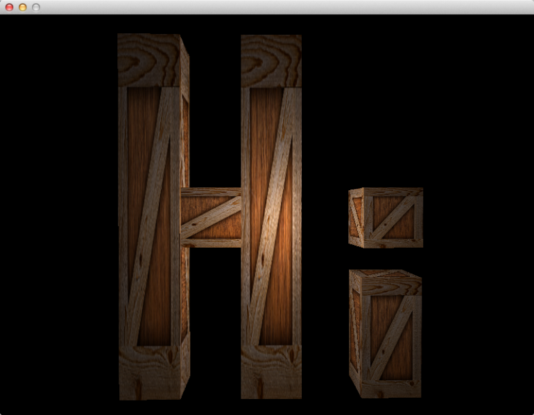
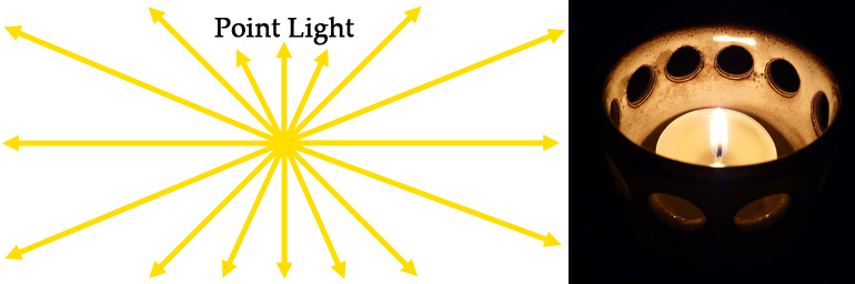
Point lights radiate light outwards in all directions from a single point, much like a candle.
In this article, we will be implementing a type of light called a point light. Point lights radiate light outwards in all directions from a single point, much like a candle. If you look at the screenshot at the top of this article, it looks like an invisible candle is being held up to the wooden crates.
There are other common types of lights, such as directional lights and spotlights, but we will cover those in a later article.
Phong Reflection Model
The Phong reflection model provides a method of calculating the color of a pixel, based on the parameters of a light source and a surface.
We will be implementing the diffuse component of the Phong reflection model. The Phong reflection model provides a method of calculating the color of a pixel, based on the parameters of a light source and a surface. The light source parameters include the position/direction of the light, and the color/intensity of the light. The surface parameters include the color of the surface, the direction the surface is facing (a.k.a the normal), and the “shininess” of the surface.
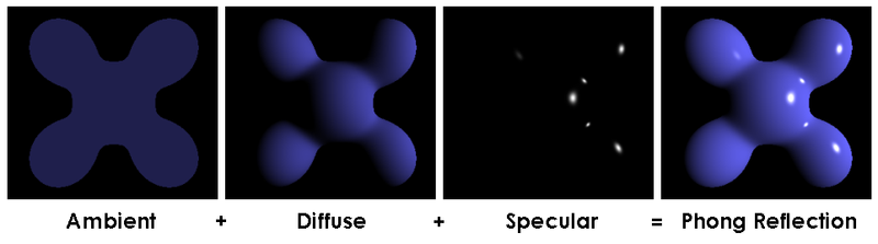
The Phong reflection model has three components: ambient, diffuse, and specular. The diffuse component is the most important one, as you can see from the image above. The ambient component is used to stop the unlit, back sides of objects from being pure black, because pure black looks artificial in most 3D scenes. The specular component is what makes an object look shiny or dull. Because we’re only implementing the diffuse component in this article, the wooden crates will be pure black on the back sides, and can not be shiny. We will implement the ambient and specular components in the next couple of articles.
Light Intensities
The Phong reflection model is loosely based on the way that light behaves in the real world. So, in order to understand lighting in OpenGL, we have to understand a little bit about the physics of light – not a lot, but just enough to make our 3D scene look more realistic.
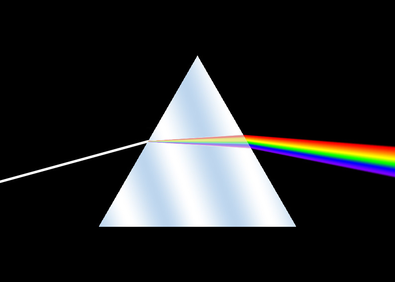
White light contains all the colors.
White light contains all the colors that our human eyes can see. This can be demonstrated by shining a white light into a prism, which makes the light split into a rainbow.
Another way to demonstrate this is by getting three different colors of light – red, green and blue – and shining them onto a white surface in a dark room. If you were to do this, you would see the image below.
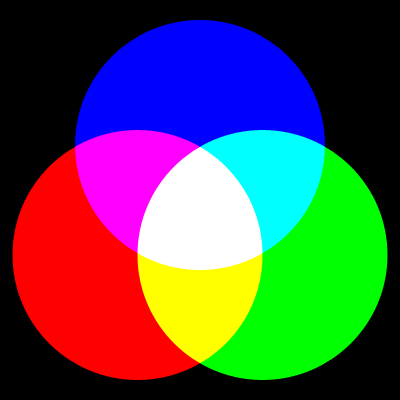
We can draw some conclusions from this:
- White = red + green + blue
- Yellow = red + green
- Cyan (light blue) = blue + green
- Magenta (purply-pink) = red + blue
- Black = none of the colors
Using only three colors of light, we can make eight different colors: red, green, blue, yellow, cyan, magenta, black and white.
But what about the other colors, like orange? Well, if you take the green light and make it half as bright as it used to be, you would see the image below.
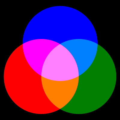
Lowering the intensity (a.k.a. brightness) of the green has made a few new colors: dark green, sky blue, orange, and pink.
Colors are combinations of different intensities of red, green and blue light.
The color of a light is called the intensities of the light.
As you can see, colors are combinations of different intensities of red, green
and blue light. This is why the color of a light is called the intensities of
the light. When we set the color of the light in the code, we will be using a
vec3 to hold the red, green and blue intensities.
Absorption & Reflection Of Color
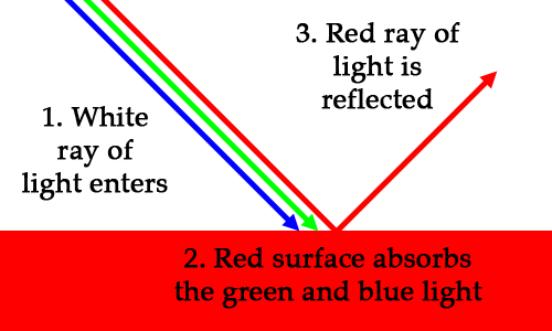
Let’s say you’re looking at a red car. The sun emits a ray of white light. The ray bounces off the car, and goes into your eye. Your eye detects that the ray only contains red light, which is why you see a red car instead of a white car. We know that white light contains all colors, so what happened to the green and blue? The green and blue light was absorbed by the surface, and the red light was reflected.
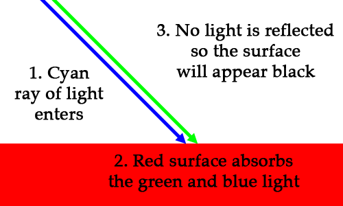
What if we were to shine a pure cyan (blue + green) light on the red car? If the car was pure red, it would look black, because it would absorb 100% of the light.
What about a cyan (blue + green) light on a magenta (red + blue) surface?
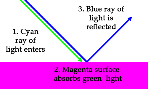
So if you shine a light-blue flashlight onto a purply-pink surface, the surface will appear to be dark blue. It’s strange, but true.
The RGB color of a surface represents how light is absorbed and reflected by that surface.
If you look at the RGB value of each color, you will notice that the values represent reflectance. (0,0,0) is black, which means reflect none of the light. (1,1,1) is white, which means reflect all of the light. (1,0,0) is red, which means only reflect the red. Cyan is (0,1,1), which means only reflect blue and green. The RGB color of a surface represents how light is absorbed and reflected by that surface.
Calculating the reflected color is simple. The basic formula is: intensities
× surface color = reflected intensities. For example:
cyan light × magenta surface = blue light
(0, 1, 1)  × (1, 0, 1)       = (0, 0, 1)
The multiplication is done by multiplying each of the RGB components individually, like so:
Angle of Incidence
Here is a lovely animation of me spinning a notepad in front of a light:

This animation demonstrates how the angle of incidence (AoI) of the light affects the color of the surface (the notepad). Notice how the notepad is brightest when it is facing the light front-on. As the notepad rotates away from it’s brightest position, the surface gets darker.
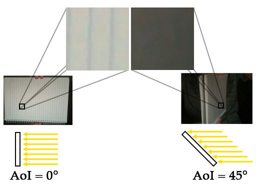
The angle at which the rays of light hit the surface is called the angle of incidence (AoI). The angle of incidence affects the brightness of a surface.
The angle at which the rays of light hit the surface is called the angle of incidence (AoI). The angle of incidence affects the brightness of the surface. The AoI is the basis of diffuse reflection, which we will implement in this article.
Let’s look at the the AoI at the two extremes: maximum brightness and complete darkness.
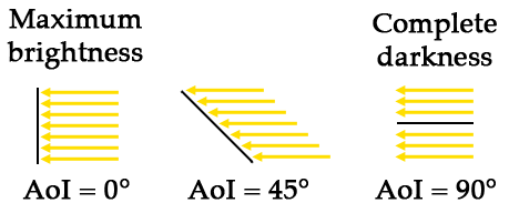
Maximum brightness occurs when the surface is perpendicular to the light rays (AoI = 0°). Complete darkness occurs when the surface is parallel to the light rays (AoI = 90°). If the AoI is greater than 90°, then the ray is hitting the back of the surface. If light is hitting the back, then it’s definitely not hitting the front, so the pixel should also be completely dark.
If we represent the brightness as a single number, where 0.0 is completely dark
and 1.0 is maximum brightness, then it’s easy to calculate based on the cosine
of the AoI. The formula is brightness = cos(AoI). Let’s have a look at the
cosine of some angles, just to prove that it works:
cos(  0°) =  1.00 (100% of maximum brightness)
cos(  5°) =  0.98 ( 98% of maximum brightness)
cos( 45°) =  0.71 ( 71% of maximum brightness)
cos( 85°) =  0.09 (  9% of maximum brightness)
cos( 90°) =  0.00 (Completely dark)
cos(100°) = -0.17 (Completely dark. Negative value means light is hitting the back side)
Once we have a brightness value between 0 and 1, we can multiply it by the intensities of the reflected light to get the final color for the pixel. Here is an example with cyan light:
brightness × light intensities = final color for pixel
1.0 × (0, 1, 1) = (0, 1, 1) (cyan, unchanged)
0.5 × (0, 1, 1) = (0, 0.5, 0.5) (turquoise, which is darkened cyan)
0.0 × (0, 1, 1) = (0, 0, 0) (black)
This “brightness” value between 0 and 1 is sometimes called the “diffuse coefficient.”
Surface Normals
Normals are unit vectors that are perpendicular (at right angle, 90°) to a surface.
In order to calculate the AoI, we first need to know the direction that each surface is facing. The direction that a surface is facing is called the normal of that surface. Normals are unit vectors that are perpendicular (at right angle, 90°) to a surface.
The angle of incidence is defined as the angle between the surface normal, and the direction to the light source.
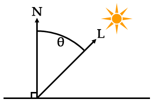
L = a vector from the surface to the light source
θ = the angle of incidence
The vector from the surface to the light source, L, can be calculated with vector subtraction, like so:
You may wish to read article 04 of this series if you need to brush up on vector math.
The surface normal is usually supplied from the VBO, the same way the vertex and texture coordinates are supplied. When we get to the code for this article, we will be adding a normal for each vertex in the VBO.
Calculating The Angle Between Two Vectors: The Dot Product
It is possible to calculate the angle between two vectors using the dot product of the vectors.
It is possible to calculate the angle between two vectors using the dot
product of the vectors. The dot product is an operation that takes two
vectors, and results in a single number (a scalar). Shockingly, the dot product
looks like a dot in mathematical notation: $$\vec{v_1}\bullet\vec{v_2}$$. In
GLSL and GLM, it is a function called “dot”: dot(v1, v2), and glm::dot(v1,
v2).
The result of the dot product is related to the angle between the two vectors. The exact relationship is:
Where $$\vec{v_1}$$ and $$\vec{v_2}$$ are vectors, $$\theta$$ is the angle between the two vectors, and $$|\vec v|$$ is the magnitude of $$\vec v$$.
The exact same thing, written like code, looks like this:
                              dot(v1,v2) == length(v1)*length(v2)*cos(angle)
      dot(v1,v2)/(length(v1)*length(v2)) == cos(angle)
acos(dot(v1,v2)/(length(v1)*length(v2))) == angle
length is a GLSL function that returns the magnitude of a vector.
We don’t actually need to know the AoI, we just need cos(AoI), which
represents brightness. The brightness calculation in the fragment shader is
based on the middle line of the formulas above.
//    cos(angle) = dot(v1, v2)                 / (length(v1) * length(v2))
float brightness = dot(normal, surfaceToLight) / (length(surfaceToLight) * length(normal));
Matrix Transformation Of Normals
Normals are usually provided in model space, which means they are relative to
the vertices of the asset before any transformations have been applied.
However, when we calculate the vector from the surface to the light, that is
done in world space. World space is where all the 3D objects have been
positioned/scaled/rotated into their places inside the 3D scene. For example,
in model space, the center of our wooden crate asset is (0,0,0). After we
position and resize the crates to spell out “Hi” in the 3D scene, those crates
are in world space. The transformation from model space to world space is done
by the “model matrix” of each instance in the scene, which is the
ModelInstance::transform variable in the code for this article.
When we transform the vertices of an asset, we also have to transform the normals.
When vertices are transformed from model space to world space, they may have been rotated. If the vertices of a surface have been rotated, then the surface now faces a different direction, so the normal of the surface will be different. This means that when we transform the vertices of an asset, we also have to transform the normals.
Scaling or translating a normal will result in an incorrect normal.
So far, we’ve only used matrices to transform coordinates. The problem is that normals are not coordinates, they are unit vectors representing directions. Rotation transformations are fine, because the rotating a unit vector results in another unit vector, but scaling or translating a normal will result in an incorrect normal. The solution is to multiply the normals by a different matrix – one that has the translation and scaling parts fixed.
Removing the translation part of a 4x4 matrix is simple: we just remove the 4th column and row, converting it to a 3x3 matrix. Fixing the scaling is a bit trickier, but I’ll jump straight to the answer, which is to invert and transpose the matrix. We will also need to renormalise each normal after it has been transformed, to ensure that it is still a unit vector. The GLSL to do this looks like:
mat3 normalMatrix = transpose(inverse(mat3(model)));
vec3 transformedNormal = normalize(normalMatrix * normal);
The model variable is the original 4x4 model transformation matrix. The
mat3 function removes the translation part of the matrix. The inverse and
transpose functions will fix up the scaling part. Finally, after we transform
the original normal with normalMatrix * normal, the normalize function will
ensure that the transformed normal is a unit vector.
The Vertex Shader
Phew! That was a lot of reading, but now we get into the code. Let’s start by looking at the vertex shader.
#version 150

uniform mat4 camera;
uniform mat4 model;

in vec3 vert;
in vec2 vertTexCoord;
in vec3 vertNormal;

out vec3 fragVert;
out vec2 fragTexCoord;
out vec3 fragNormal;

void main() {
    // Pass some variables to the fragment shader
    fragTexCoord = vertTexCoord;
    fragNormal = vertNormal;
    fragVert = vert;

    // Apply all matrix transformations to vert
    gl_Position = camera * model * vec4(vert, 1);
}
This is mostly the same as the last article. The main difference is that we
have a new input variable for the surface normals called vertNormal. Also, we
send three variables straight through to the fragment shader without modifying
them: the vertex, the normal, and the texture coordinate.
The Fragment Shader
Now let’s look at the fragment shader, where all of the lighting calculations are done.
#version 150

uniform mat4 model;
uniform sampler2D tex;

uniform struct Light {
   vec3 position;
   vec3 intensities; //a.k.a the color of the light
} light;

in vec2 fragTexCoord;
in vec3 fragNormal;
in vec3 fragVert;

out vec4 finalColor;

void main() {
    //calculate normal in world coordinates
    mat3 normalMatrix = transpose(inverse(mat3(model)));
    vec3 normal = normalize(normalMatrix * fragNormal);

    //calculate the location of this fragment (pixel) in world coordinates
    vec3 fragPosition = vec3(model * vec4(fragVert, 1));

    //calculate the vector from this pixels surface to the light source
    vec3 surfaceToLight = light.position - fragPosition;

    //calculate the cosine of the angle of incidence
    float brightness = dot(normal, surfaceToLight) / (length(surfaceToLight) * length(normal));
    brightness = clamp(brightness, 0, 1);

    //calculate final color of the pixel, based on:
    // 1. The angle of incidence: brightness
    // 2. The color/intensities of the light: light.intensities
    // 3. The texture and texture coord: texture(tex, fragTexCoord)
    vec4 surfaceColor = texture(tex, fragTexCoord);
    finalColor = vec4(brightness * light.intensities * surfaceColor.rgb, surfaceColor.a);
}
We have a new shader uniform called light, which is a struct containing the
position and the intensities/color of the light.
The variables fragTexCoord, fragNormal and fragVert all come straight
from the vertex shader. fragTexCoord is the texture coordinate, as we’ve seen
in previous articles. fragNormal is the untransformed surface normal for
this fragment/pixel. fragVert is the untransformed coordinate of the
surface that we are drawing.
The first part of main transforms the normal into world space, as explained
in the previous section of this article.
mat3 normalMatrix = transpose(inverse(mat3(model)));
vec3 normal = normalize(normalMatrix * fragNormal);
The next part transforms the surface coordinate fragVert into world space.
vec3 fragPosition = vec3(model * vec4(fragVert, 1));
The model uniform is a 4x4 matrix, so we convert the coordinate to a vec4 in
order to do the transformation, then we convert back to vec3.
Next, we calculate a vector from the surface coordinate to the light coordinate, both of which are in world space.
vec3 surfaceToLight = light.position - fragPosition;
Next, we calculate the brightness, which is equal to cos(angleOfIncidence).
As explained earlier in the article, we use the dot product of the normal and a
vector pointing towards the light.
float brightness = dot(normal, surfaceToLight) / (length(surfaceToLight) * length(normal));
Remembering that brightness can be negative – which indicates that the light is hitting the back of the surface – we restrict the brightness to a value between 0 and 1. Negative values will become 0, which means completely dark.
brightness = clamp(brightness, 0, 1);
Finally, using the brightness, the light intensities and the surface color, we can calculate the color of the fragment/pixel.
vec4 surfaceColor = texture(tex, fragTexCoord);
finalColor = vec4(brightness * light.intensities * surfaceColor.rgb, surfaceColor.a);
texture(tex, fragTexCoord) will get the color of the surface from the
texture. This surface color determines how the intensities of the light are
reflected or absorbed. Remember the formula intensities × surface color =
reflected intensities. We are implementing that here with the code
light.intensities * surfaceColor.rgb.
After we calculate the reflected intensities with light.intensities *
surfaceColor.rgb, we multiply them by brightness to get the
final color. Multiplying by the brightness will darken the reflected
intensities based on the angle of incidence.
The light intensities are a vec3 (RGB), but the final color is a vec4
(RGBA), so we convert the intensities to a vec4 and set the alpha channel to
the alpha value from the texture: surfaceColor.a. This means the rendered
surface will be transparent wherever the texture is transparent.
Changes In main.cpp
The majority of lighting is done in the fragment shader, so the C++ code changes are fairly minor.
We have a new global called gLight that is an exact copy of the light struct
in the fragment shader.
struct Light {
    glm::vec3 position;
    glm::vec3 intensities; //a.k.a. the color of the light
};

// ...

Light gLight;
We update the VBO to include a normal for each vertex. The old buffer data looked like this:
//  X     Y     Z       U     V
//bottom
-1.0f,-1.0f,-1.0f,   0.0f, 0.0f,
 1.0f,-1.0f,-1.0f,   1.0f, 0.0f,
-1.0f,-1.0f, 1.0f,   0.0f, 1.0f,
 1.0f,-1.0f,-1.0f,   1.0f, 0.0f,
 1.0f,-1.0f, 1.0f,   1.0f, 1.0f,
-1.0f,-1.0f, 1.0f,   0.0f, 1.0f,
//...
And now it looks like this:
//  X     Y     Z       U     V          Normal
//bottom
-1.0f,-1.0f,-1.0f,   0.0f, 0.0f,   0.0f, -1.0f, 0.0f,
 1.0f,-1.0f,-1.0f,   1.0f, 0.0f,   0.0f, -1.0f, 0.0f,
-1.0f,-1.0f, 1.0f,   0.0f, 1.0f,   0.0f, -1.0f, 0.0f,
 1.0f,-1.0f,-1.0f,   1.0f, 0.0f,   0.0f, -1.0f, 0.0f,
 1.0f,-1.0f, 1.0f,   1.0f, 1.0f,   0.0f, -1.0f, 0.0f,
-1.0f,-1.0f, 1.0f,   0.0f, 1.0f,   0.0f, -1.0f, 0.0f,
//...
The vertices shown above make up the bottom face of the wooden crate. Notice how they all have the same normal, (0, -1, 0), which is a unit vector pointing straight down the Y axis. There are six faces on the wooden crate, and each face has a normal that points directly down the positive or negative direction of the X, Y, or Z axis.
Because the format of the VBO has changed to include normals, we have to change the VAO as well. This is the old VAO setup code:
// connect the xyz to the "vert" attribute of the vertex shader
glEnableVertexAttribArray(gWoodenCrate.shaders->attrib("vert"));
glVertexAttribPointer(gWoodenCrate.shaders->attrib("vert"), 3, GL_FLOAT, GL_FALSE, 5*sizeof(GLfloat), NULL);

// connect the uv coords to the "vertTexCoord" attribute of the vertex shader
glEnableVertexAttribArray(gWoodenCrate.shaders->attrib("vertTexCoord"));
glVertexAttribPointer(gWoodenCrate.shaders->attrib("vertTexCoord"), 2, GL_FLOAT, GL_TRUE,  5*sizeof(GLfloat), (const GLvoid*)(3 * sizeof(GLfloat)));
And this is the new VAO setup code:
// connect the xyz to the "vert" attribute of the vertex shader
glEnableVertexAttribArray(gWoodenCrate.shaders->attrib("vert"));
glVertexAttribPointer(gWoodenCrate.shaders->attrib("vert"), 3, GL_FLOAT, GL_FALSE, 8*sizeof(GLfloat), NULL);

// connect the uv coords to the "vertTexCoord" attribute of the vertex shader
glEnableVertexAttribArray(gWoodenCrate.shaders->attrib("vertTexCoord"));
glVertexAttribPointer(gWoodenCrate.shaders->attrib("vertTexCoord"), 2, GL_FLOAT, GL_TRUE,  8*sizeof(GLfloat), (const GLvoid*)(3 * sizeof(GLfloat)));

// connect the normal to the "vertNormal" attribute of the vertex shader
glEnableVertexAttribArray(gWoodenCrate.shaders->attrib("vertNormal"));
glVertexAttribPointer(gWoodenCrate.shaders->attrib("vertNormal"), 3, GL_FLOAT, GL_TRUE,  8*sizeof(GLfloat), (const GLvoid*)(5 * sizeof(GLfloat)));
It’s basically the same, with the addition of the normals.
Now let’s look at how rendering has changed inside the RenderInstance
function. Before we render each instance, all we have to do is set the position
and color of the light in the shaders. We take the position and intensities
straight out of the gLight global.
shaders->setUniform("light.position", gLight.position);
shaders->setUniform("light.intensities", gLight.intensities);
Next, let’s look at the new keyboard controls to change the light inside of the
Update function.
//move light
if(glfwGetKey(gWindow, '1'))
    gLight.position = gCamera.position();

// change light color
if(glfwGetKey(gWindow, '2'))
    gLight.intensities = glm::vec3(1,0,0); //red
else if(glfwGetKey(gWindow, '3'))
    gLight.intensities = glm::vec3(0,1,0); //green
else if(glfwGetKey(gWindow, '4'))
    gLight.intensities = glm::vec3(1,1,1); //white
Pressing the 1 key sets the position of the light to the current position of the camera. Moving the light around will allow us to observe how the angle of incidence affects the brightness of the surfaces.
Pressing the 2, 3, and 4 keys will change the color of the light.
Inside the AppMain function we set the initial position and color of the
light when the program starts.
gLight.position = gCamera.position();
gLight.intensities = glm::vec3(1,1,1); //white
Lastly, there are a couple of changes that are unrelated to lighting. I increased the movement speed of the camera, because it seemed a bit slow. I also increased the near plane distance of the camera from 0.01 to 0.5, because 0.01 was too small, and it as causing weird jagged edges to appear on the wooden crates.
gCamera.setNearAndFarPlanes(0.5f, 100.0f);
That’s it! We now have a single, diffuse, point light. This is the first step in 3D lighting, and we will build upon it in the next couple of articles.
Per-vertex Vs Per-fragment Lighting
Per-fragment lighting looks better than per-vertex lighting, which is one good reason to switch from the old fixed-function pipeline to shaders.
In this article we’ve implemented per-fragment lighting, also known as Phong shading – not to be confused with the Phong reflection model. We could have chosen, instead, to implement per-vertex lighting, also known as Gouraud shading. The difference between the two implementations is where the lighting calculations are performed: in the fragment shader, or in the vertex shader. The old OpenGL fixed-function pipeline implemented per-vertex shading, if you wanted per-fragment lighting you had to write your own shaders. Per-fragment lighting looks better than per-vertex lighting, which is one good reason to switch from the old fixed-function pipeline to shaders.
If we chose per-vertex lighting, the brightness would be calculated at each vertex – that is, at each corner of the wooden crates. Then, the brightness would be interpolated across all the pixels in each triangle. For example, if one corner was dark, and the other was bright, the pixels in between the two corners would fade from dark to bright. Now let’s look at one of the crates in the screenshot for this article:
Notice how all of the corners are dark, because the bright area is right in the middle of the surface. If we had implemented per-vertex lighting, this would look horrible. All the corners are dark, so the entire surface would be dark too. It would look wrong, as if there was no light in front of the surface.
This is the problem with per-vertex lighting – it often looks wrong, especially if the vertices of the model are far apart. One solution is to increase the number of vertices in the model. The two images below show per-vertex lighting applied to two spheres: one with few vertices (low-poly), and one with lots of vertices (high-poly).
The low-poly sphere has a weird pentagon-shaped highlight, but the high-poly sphere has a circular highlight that looks more correct.
Using per-fragment lighting, we sidestep this problem. Instead of calculating the brightness at each corner of the wooden crates, we calculate the brightness at each pixel. This why per-fragment lighting looks better than per-vertex lighting: it’s doing more lighting calculations per surface, so it’s more accurate.
Per-vertex lighting is generally faster than per-fragment lighting.
There is a tradeoff, however. Per-vertex lighting requires three calculations per triangle. Per-fragment lighting requires one calculation per fragment that the triangle covers, which is usually a lot more than three. Also, increasing the screen resolution increases the number of fragments per triangle. More calculations means that rendering takes longer, so per-vertex lighting is generally faster than per-fragment lighting. Modern desktop hardware can handle per-fragment lighting fairly easily, but the speed difference can still be an issue for older hardware and mobile devices.
Future Article Sneak Peek
In the next few articles, we will be implementing more aspects of lighting. We will be implementing the ambient and specular components of the Phong reflection model. We will also look at other types of light: directional lights, and spotlights.
Additional Resources
- Tutorial 8 : Basic shading from opengl-tutorial.org
- Chapter 4: Rendering a Dynamic 3D Scene with Phong Shading of Joe Groff’s An intro to modern OpenGL.
- From the Learning Modern 3D Graphics Programming book:
- Tutorial 18 - Diffuse Lighting of OGLdev Modern OpenGL Tutorials
- From the OpenGL programming wikibook book:
- Related Wikipedia articles: